

How to Read an FLS Drawing: A Beginner’s Guide
If you’ve ever unrolled a set of construction plans and felt your eyes glaze over at a page full of tiny symbols, circles, and dashed lines, you’re not alone. For engineers, contractors, facility managers, and even property owners, learning how to read an FLS drawing is one of the most valuable skills you can pick up in the built-environment industry. It’s the difference between confidently reviewing a fire safety layout and simply nodding along in a meeting.
This guide breaks down exactly what an FLS drawing is, why it matters, and how to read one step by step — even if you’ve never opened a fire protection plan before.
What Is an FLS Drawing?
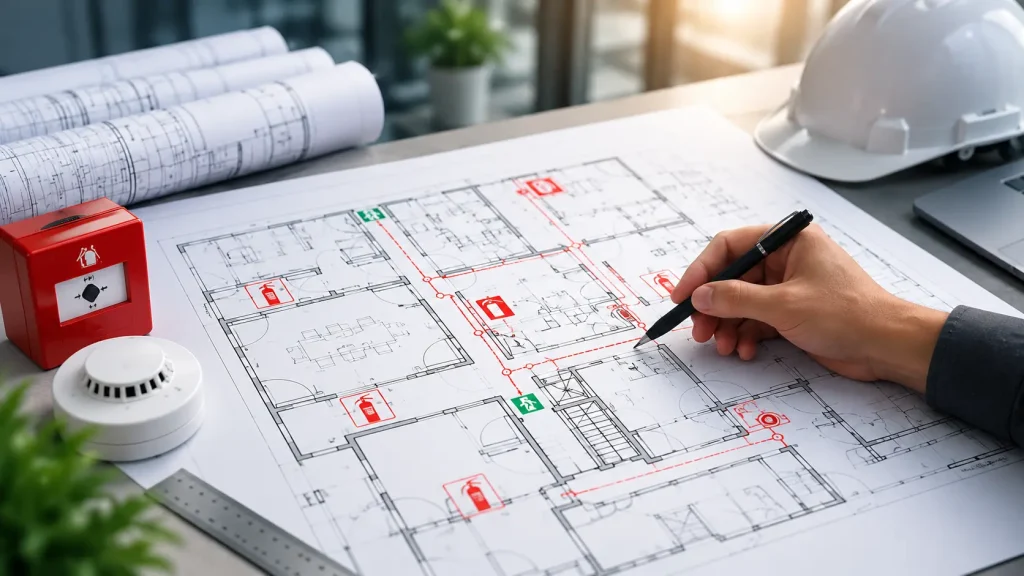
FLS stands for Fire and Life Safety. An FLS drawing is a technical plan that shows how a building’s fire detection, alarm, suppression, and evacuation systems are designed and laid out. It typically includes the placement of smoke detectors, sprinkler heads, fire alarm panels, fire extinguishers, emergency exits, fire-rated walls, and evacuation routes.
These drawings are prepared by MEP (Mechanical, Electrical, and Plumbing) or fire protection engineers and are submitted to civil defense or fire authorities for approval before construction begins. If you want a deeper look at why these systems matter in the first place, our detailed breakdown of FLS system design explains the engineering principles behind them.
Why Learning to Read an FLS Drawing Matters
Whether you’re a project manager coordinating with contractors, a building owner reviewing compliance documents, or a student entering the MEP field, understanding an FLS drawing helps you:
- Verify that fire safety equipment is placed correctly and meets code requirements
- Spot potential gaps in coverage before construction begins
- Communicate more effectively with fire protection engineers and inspectors
- Avoid costly rework caused by misinterpreted plans
- Speed up the approval process with civil defense authorities
A misread drawing can lead to missed sprinkler zones, blocked emergency exits, or non-compliant equipment placement — all of which can delay a project or, worse, compromise safety.
Step 1: Start With the Title Block
Every FLS drawing has a title block, usually located in the bottom-right corner. This section tells you:
- The drawing number and revision
- The project name and location
- The scale of the drawing
- The date it was issued
- The name of the engineer or firm responsible
Always check the revision number first. Fire safety drawings are updated frequently during a project, and working from an outdated version is one of the most common (and costly) mistakes on-site teams make.
Step 2: Understand the Legend and Symbols
The legend is your key to decoding the entire drawing. FLS drawings use standardized symbols to represent different components. While symbol styles can vary slightly between firms, common ones include:
- Circles with a cross or “S” — smoke detectors
- Circles with an “H” — heat detectors
- Small triangles or squares — sprinkler heads (upright, pendant, or sidewall types are usually distinguished by shading or orientation)
- Bell or rectangle icons — alarm bells or notification devices
- A shield or extinguisher icon — portable fire extinguisher locations
- Bold or hatched lines — fire-rated walls or partitions
- Arrows — evacuation or egress routes
Before reviewing any part of the actual layout, spend a few minutes matching every symbol on the page to its legend entry. Skipping this step is the fastest way to misread a plan.
Step 3: Read the Floor Layout
Once you know the symbols, look at how they’re distributed across the floor plan. Pay attention to:
- Coverage spacing — Sprinkler heads and detectors should be spaced according to code-mandated maximum distances, not randomly placed.
- Zoning — FLS drawings often divide a building into fire alarm zones, shown as outlined sections or color-coded areas. Each zone corresponds to a specific area monitored by the fire alarm control panel.
- Egress paths — evacuation routes should lead clearly to marked exits without passing through areas that could be blocked by fire or smoke.
- Fire-rated barriers — check that walls separating different fire zones or stairwells are marked with the correct fire-resistance rating (e.g., 1-hour, 2-hour).
Step 4: Cross-Check With Other Drawings
An FLS drawing rarely stands alone. It’s typically read alongside architectural floor plans, HVAC drawings (since duct penetrations affect fire-rated walls), and electrical layouts (since fire alarm wiring needs coordination with power distribution). If a sprinkler head appears to clash with a light fixture or duct run in another drawing, that’s a coordination issue that needs to be flagged before construction.
Step 5: Check Compliance Notes and Schedules
Most FLS drawings include a notes section or schedule table listing:
- Applicable fire codes and standards (such as NFPA or local civil defense requirements)
- Equipment specifications (pump ratings, sprinkler K-factors, detector sensitivity)
- Installation requirements or exceptions
These notes often carry legal weight during inspections, so they shouldn’t be skipped even if the visual layout looks straightforward.
Common Mistakes Beginners Make
- Confusing detector types (smoke vs. heat) because the symbols look similar at a glance
- Overlooking the drawing’s scale, leading to incorrect distance assumptions
- Not checking for the latest revision before starting work
- Ignoring zone boundaries when assessing alarm coverage
Final Thoughts
Reading an FLS drawing isn’t about memorizing every possible symbol overnight — it’s about building a systematic habit: check the title block, study the legend, trace the layout, cross-reference other trades, and read the compliance notes. With practice, what once looked like a maze of circles and lines becomes a clear, logical map of how a building protects the people inside it.
If your project needs a professionally engineered fire safety layout rather than just help interpreting one, our team specializes in complete FLS system designing service — from initial concept through civil defense approval.
